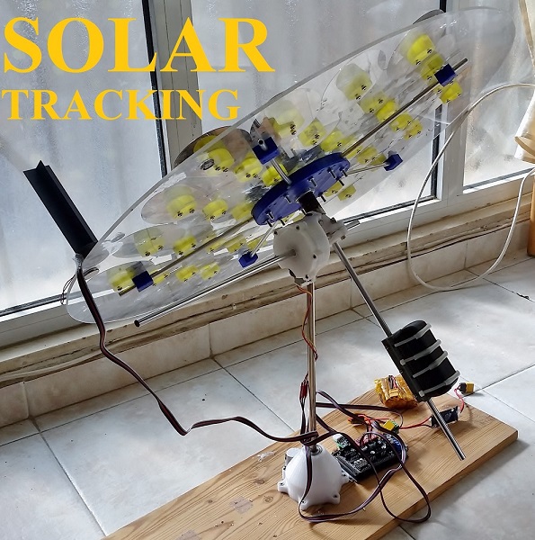
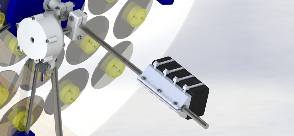
This post is a follow-up to the former blog post about the solar cooker. The mirror array can now track the sun and rotate toward it. Here I will give a full description of the design and building process, alongside with explanation about the tracking algorithm.
The tracking device is quite easy to build (though challenging to design), it is made out of three stainless steel rods, two stepper motors, a solar sensing device, a RAMPS/MKS controller, ball bearings and 3D printed parts for the frame and torque transmission.

Skeleton
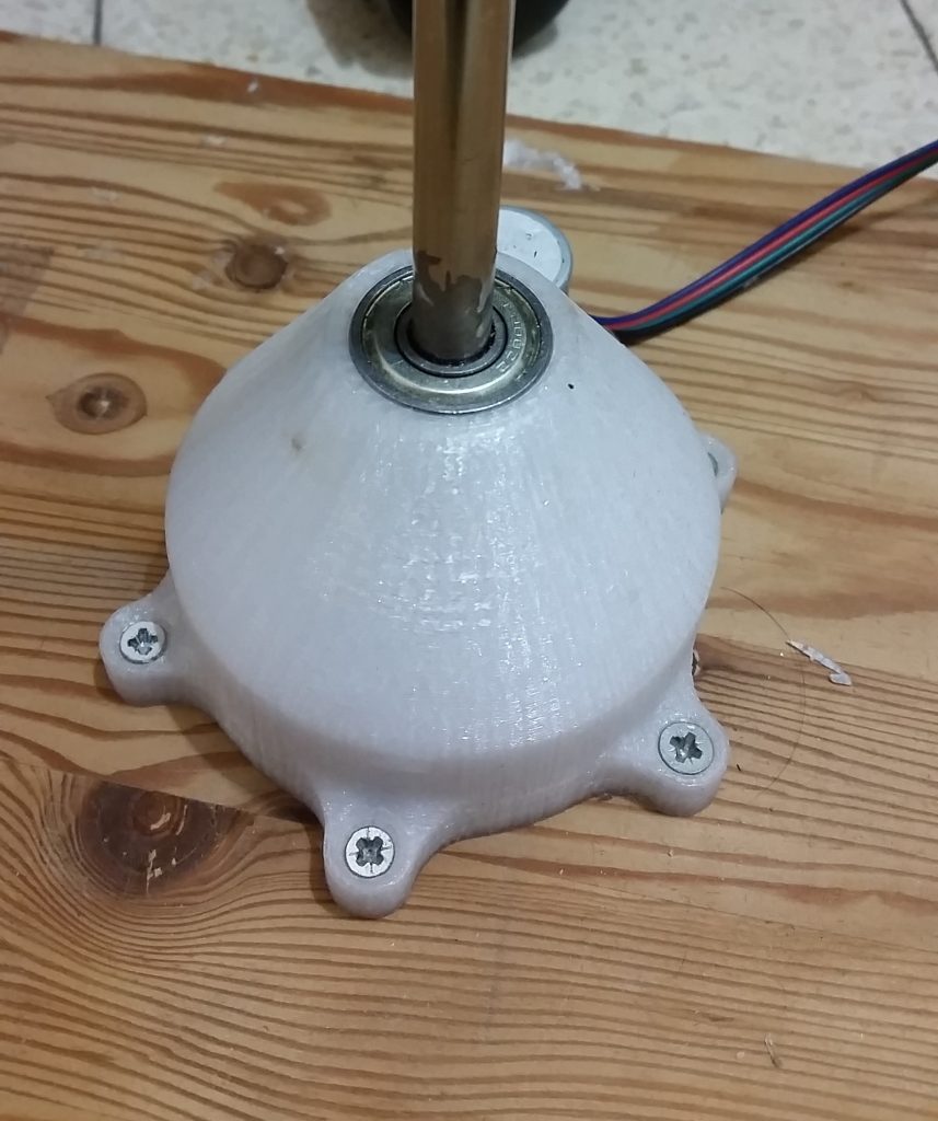
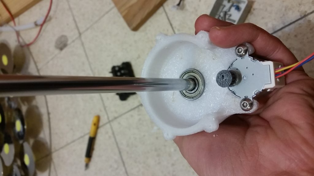
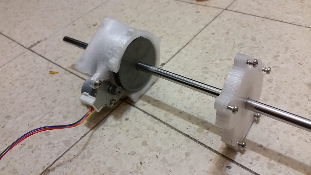
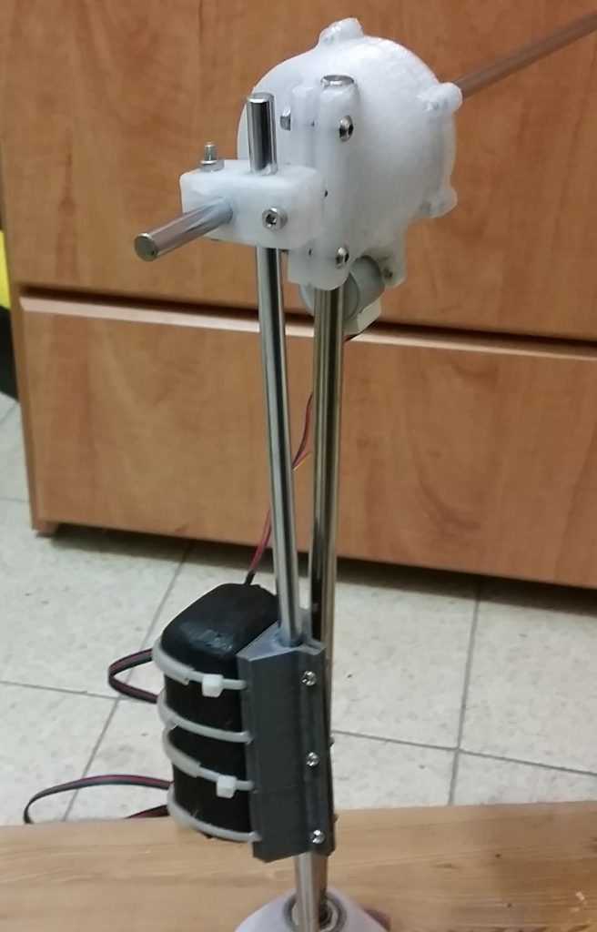
The base of the device is 3D printed and shaped like a cone, it has small ears that are meant to be fastened to a wide wooden base with countersink self-tapping screws. Two bearings (6000Z) are pressure inserted to the base, providing low friction for azimuth rotation of the shaft (10X415mm stainless steel) and stiffness against bending moments on the other axis of rotation.

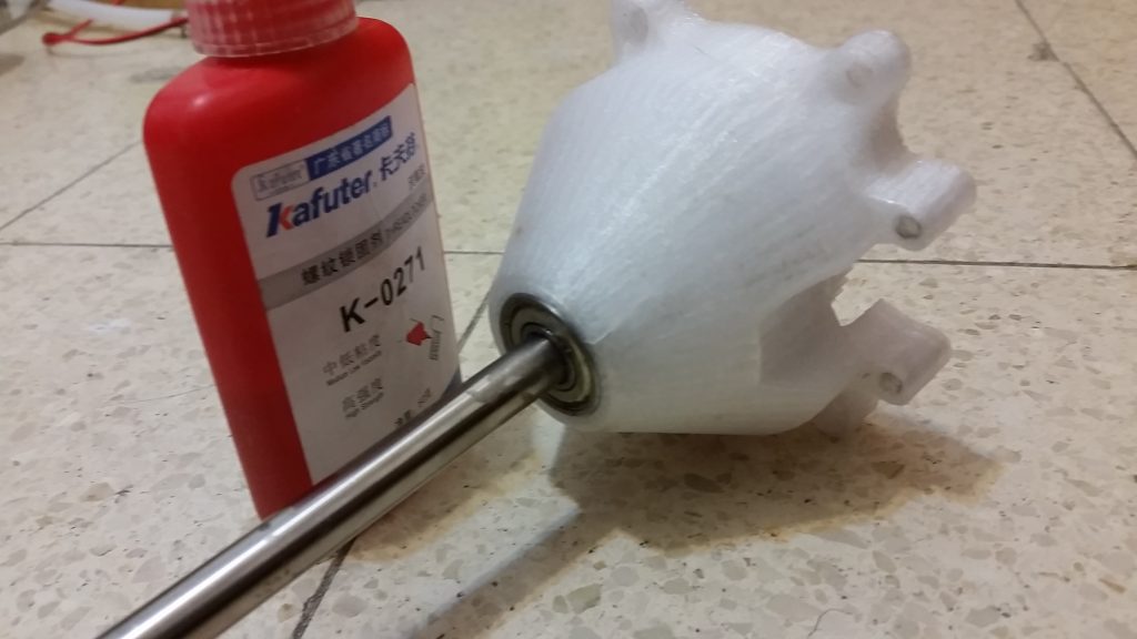
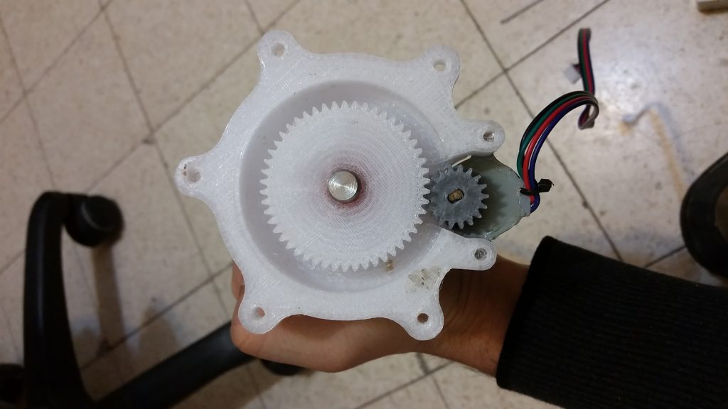
The base also mounts a stepper motor and hides a larger gear attached to the azimuth shaft. The larger gear is glued with Loctite to the azimuth shaft and is driven by a smaller gear mounted on the stepper motor, providing the motor with additional torque.
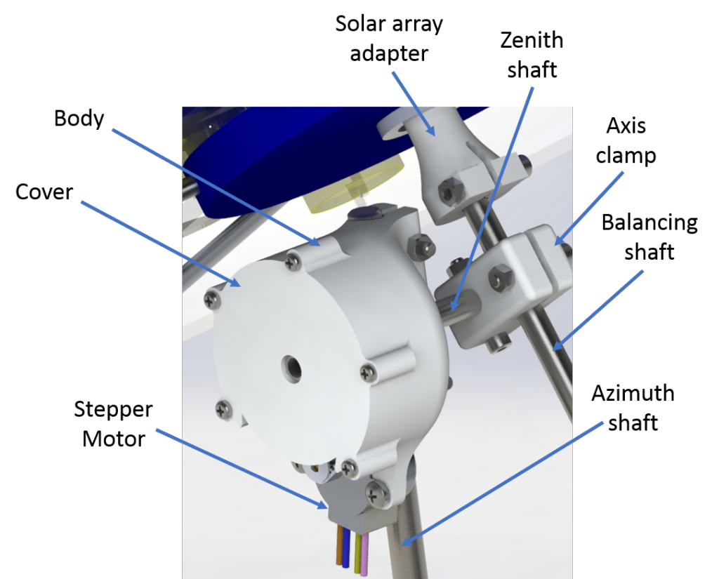
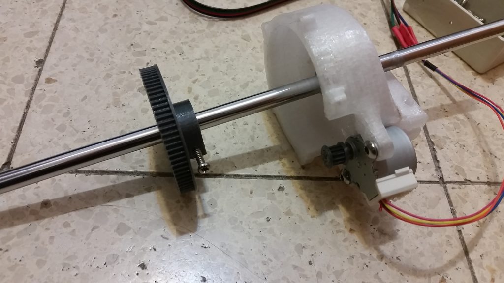
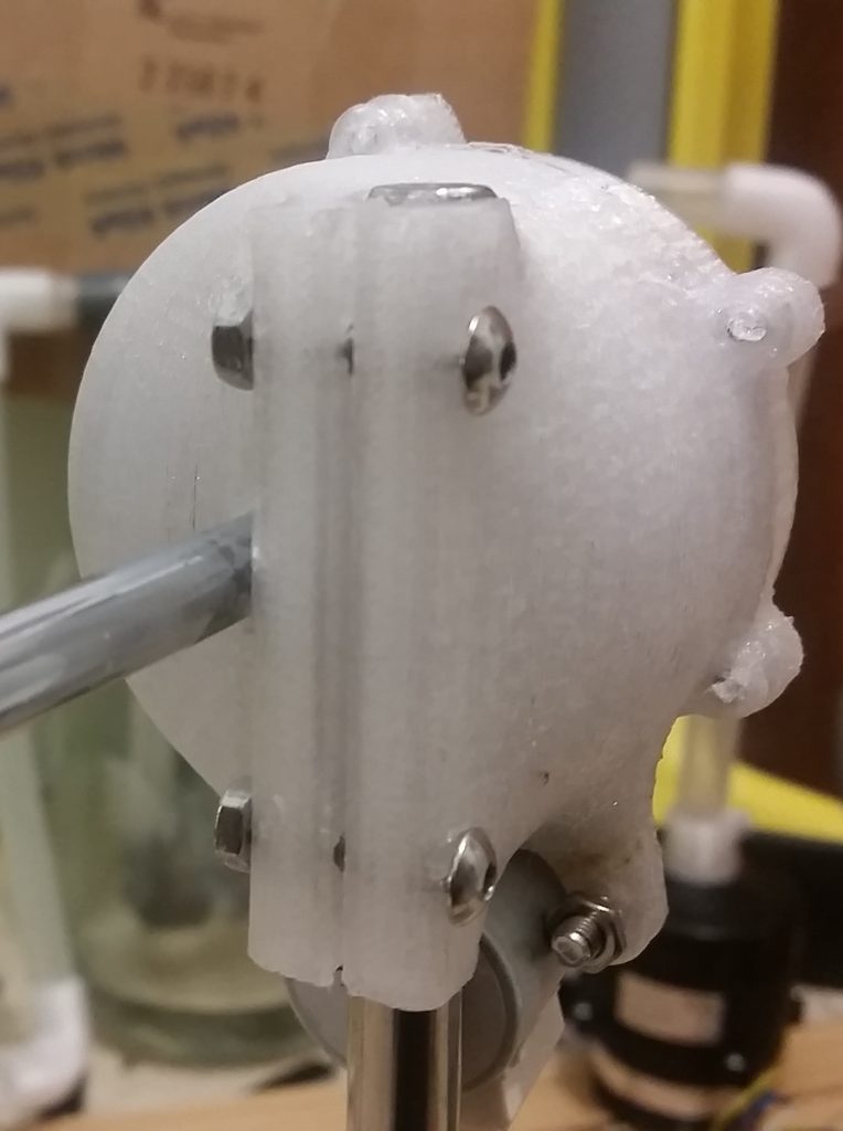
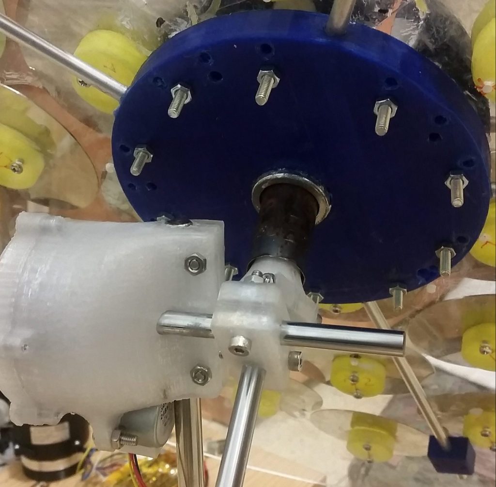
The zenith shaft is mounted on the zenith base, which is a 3D printed part with two functions: first, it mounts the zenith shaft (8x90mm stainless/aluminum) on two bearings which provide rigidity and freedom of rotation, and second, it provides additional torque for the stepper motor by a pulley gear transmission.
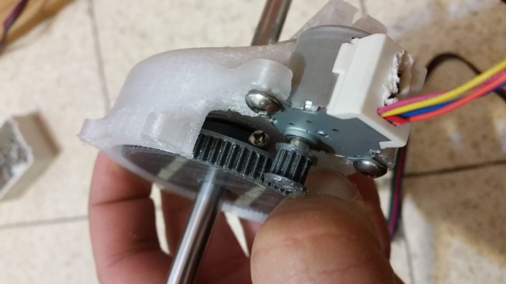
The zenith base is composed of two parts – a body, and a cover. The zenith shaft is fitted inside of the two bearings, one at the cover and the other on the body, where it is also glued with Loctite (though superglue is just as appropriate). A transmission mechanism is hidden inside the zenith base, and is implemented using two pulley gears and a rubber pulley.
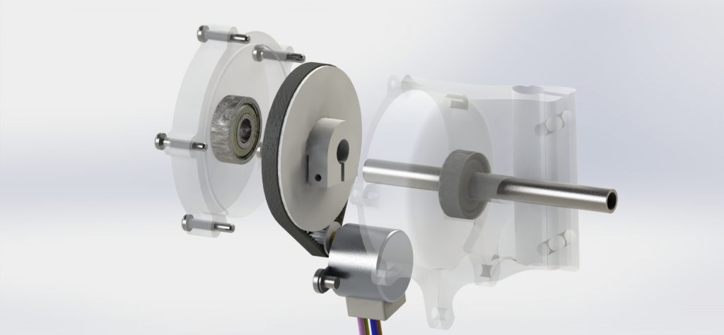
I have used a pulley transmission instead of gear transmission because zenith rotation requires some extra torque in comparing with the azimuth axis, as it needs to overcome small torque imbalance of the mirror array and the counterweight. The explanation is such that small pulley can be 3D printed much smaller than a spur gear, providing much higher torque for the zenith rotation.
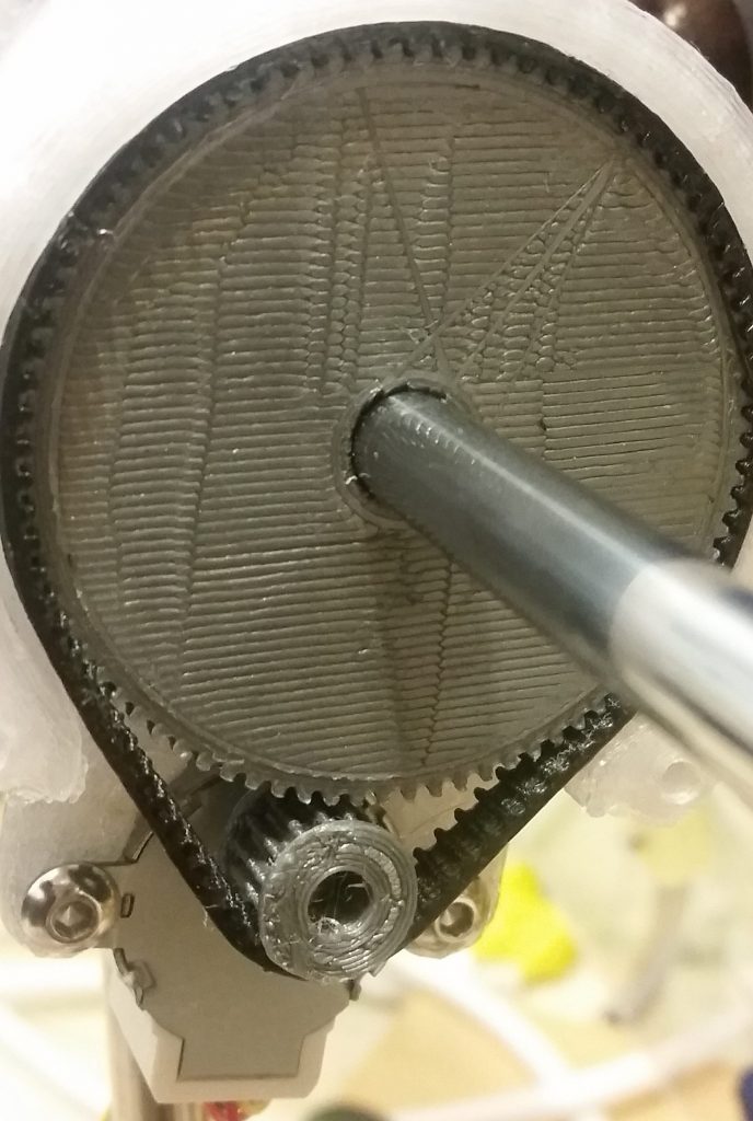
The pulley is 3D printed using TPU filament by Creozole (widely sold on Amazon and Aliexpress), and it is both functional and very durable. In fact, I was very surprised that I couldn’t find anyone else who has printed their own custom TPU pulley. It saves the trouble of loop closing stock pulley, which requires A LOT of technique.
Even with the transmission, the stepper motor is still too weak to overcome the torque of the weight of the mirror array. This was solved by adding a 900 gr counter-weight, strapped to a slider with zip ties. The slider is clamped to the balancing shaft (8×350 mm stainless) in a position where it balances the torque.
Solar Tracking sensor
To track the sun I’ve used stepper motor and feedback from a solar sensor. Any diversion from the main source of light in the azimuth or zenith angle would result in a correction signal from the sensor for the corresponding motor.
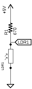
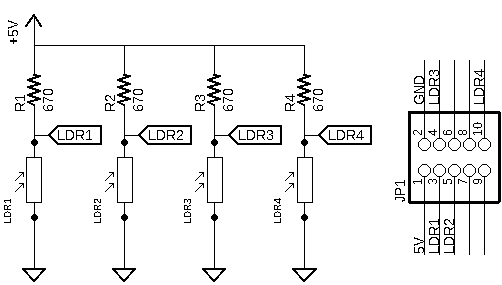
The LDRs are pulled up with ~600 Ohms, providing good sensitivity under direct sunlight (the resistor value should be about the same as the LDR under sunlight). When an LDR is shadowed or even partly shadowed, the voltage drops drastically. by comparing the LDR signal on two opposite sides we can get a very strong correction signal.
The sensor is aligned so that 2,3 and 4,1 are displaced along the zenith rotation, and 1,4 and 3,4 are displaced along the azimuth rotation. Using this calibration we can write:
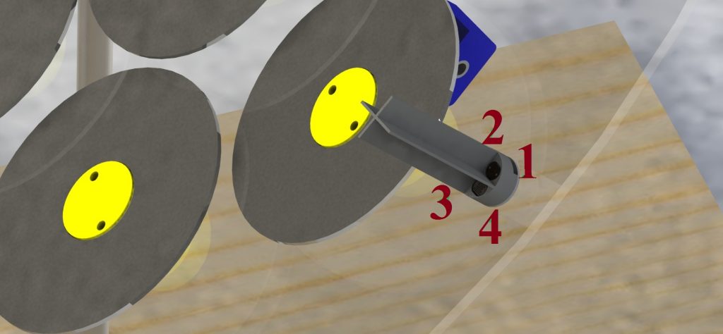
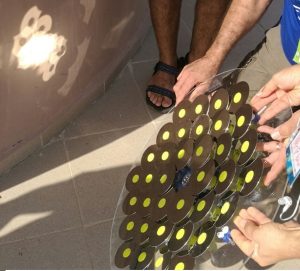
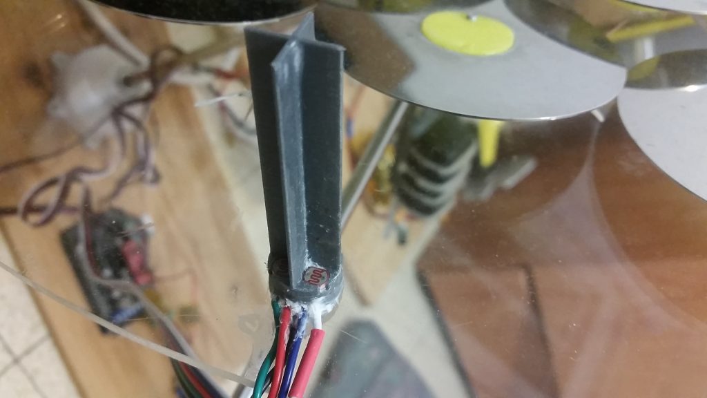
P.S – I don’t know the proper model name for the LDR I used, but you can try buying one that has the same slithering geometry as seen in the images above. These should probably produce similar results, as most sensors use the same semi-conductors materials.
Motors
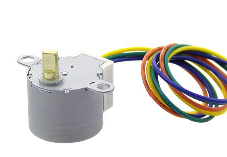
The motors used in this project are 12V stepper motors with an internal gear (28BYJ-48). These motors are very easy to find in Aliexpress and are very cheap. Although they are originally designed as a unipolar stepper motor, incompatible with the RAMPS style stepper modules, they can be modified to a bipolar stepper motor very easily, as I will show in the assembly section. For those who are curious about stepper motors, the difference between unipolar and bipolar motors, and the implications of the modification, check out this article.
Controller
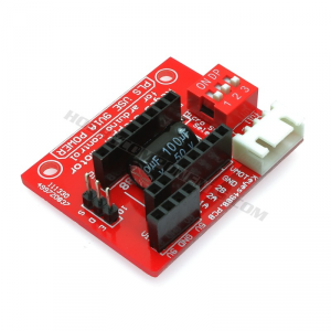
The solar tracking cooker is controlled with an ATMEGA2560 with a RAMPS 1.4 shield (or MKS gen 1.4 which is fully compatible). It makes connecting the stepper drivers and motor very standard and easy, and requires soldering a small pull-up board for the 4 LDRs of the solar sensor.

Alternatively, you can use an Arduino nano, only needing to change the pin names in the Arduino code. Also, I recommend buying stepper driver modules so you can save yourself the trouble of soldering or wiring breadboards (been there done that, its a waste of time).
Fabrication and Assembly
I really do hope that you find this project interesting enough that you would actually want to build it, or at least use the azimuth-zenith axis system, because it is quite cheap and easy to build and can be used for other uses (such as a radio telescope).
This is why I’ve uploaded the MCAD design and the code files to GrabCAD. The project folder is separated into three subfolders:
- Solidworks (version 2017) – with the original mechanical design files.
- Arduino code file – covers the program for controlling the motor and light tracking.
- 3D print files – contains the files that need to be 3D printed.
3D Printing the parts
All skeletal parts were 3D printed with mechanical strength in mind, I have 3D printed them using PETG plastic at the 250°C, 0.16mm layer height, 1.2mm shell, and ~30% infill.
The gears, the pulleys, and the solar sensor body are not stressed as much and can be printed using settings that benefit geometric accuracy over strength.
The belt is printed from a TPU filament (I’ve used Creozole’s TPU). I want to point out that I had also printed a belt from the very popular Ninja-Flex plastic and found it much more flexible than the belts sold on the marker, so I think it would be a bad choice of material.
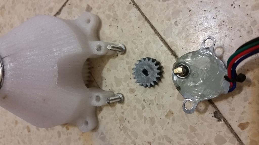
Stepper motor modification
As mentioned before, the stepper motor is unipolar and should be modified to work with the common ramps driver module, as they are designed to drive bipolar stepper motors.
All we need to do is to cut the conductor that connects the middle of the two poles in the motor, and more specifically, cut a trace on a small PCB that hides behind the plastic cover of the motor. We begin with revealing the PCB and the trace:
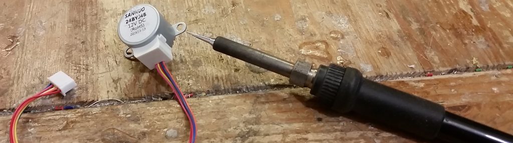
I have used my old Hakko soldering iron (replaced by the godly TS100) with low-temperature settings (~200°C) to reveal the PCB, and made a vertical cut with crafting knife to the copper trace:
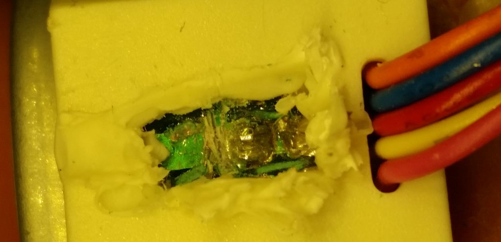
And that’s it! we now have a bipolar motor! keep in mind that the red wire is now useless and the coil poles are now connected to red-purple, and orange-blue. If you find this subsection confusing, just go to the blog post mentioned before, where the photos are better and the explanation more elaborate.
Azimuth base
After printing all the parts, we shall start by snapping in the two 10mm bearings at the top and the bottom of the azimuth base, and gluing the azimuth shaft to the two bearings using Loctite glue:
We then mount the azimuth drive gear on the stepper motor. It requires some manual force but is quite easy with the help of a locking plier or a vice. The next step is to fasten the stepper motor to the base using two M4 screws (8-14mm long):
We then glue the azimuth gear to the azimuth shaft using Loctite:
Now we shall fasten the azimuth base to a wide wooden base:
Zenith base
First, a stepper motor is press-fitted with the zenith motor pulley, and then it is mounted to the zenith base using M4 (longer than 6mm) screws and nuts:
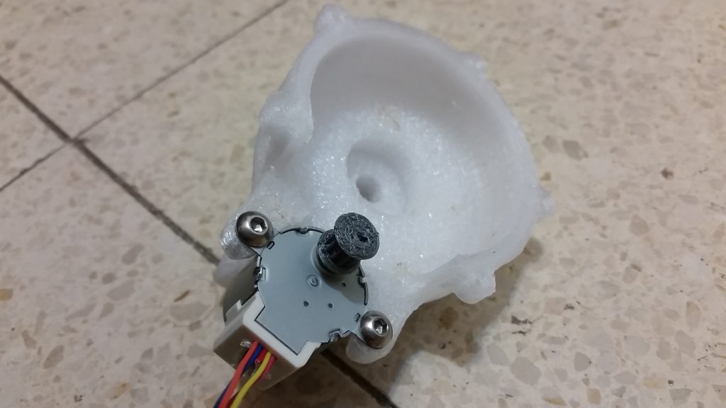
The 8mm bearing is press-fitted to the zenith base, the 8mm shaft is inserted (it is far too long than it should be, I was too lazy to cut stainless steel), and the two are glued together with Loctite, in such a way that the far end of the zenith shaft is 40mm away from the azimuth shaft to the direction of the back of the stepper motor (you are right to be confused, so just go ahead look at the assembly file on GrabCAD).
next, we slide in the zenith pulley and clamp it to the shaft with M3x20mm plastic tapping screw (I highly recommend using these screws, as machine screws do a terrible job at self-tapping to plastic):
Afterward, the belt is stretched over the two pulleys:
Then the azimuth base cover is press-fitted with another 8mm bearing:
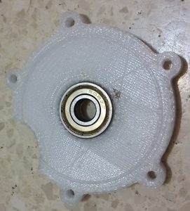
The azimuth base cover is then slid on the zenith shaft and screwed tightly in place with M3.5x12mm plastic self-tapping screws:
Now that the zenith base is fully assembled, it is to be clamped to the top of the azimuth shaft using M4 machines screws (longer than 22mm) and nuts:
Balancing weight
We then strap the weight to the weight holder with zip ties. I recommend covering the zip ties with a silicone tube (sold cheaply as a fish tank air bubble tube) to add friction against the weight slipping off.
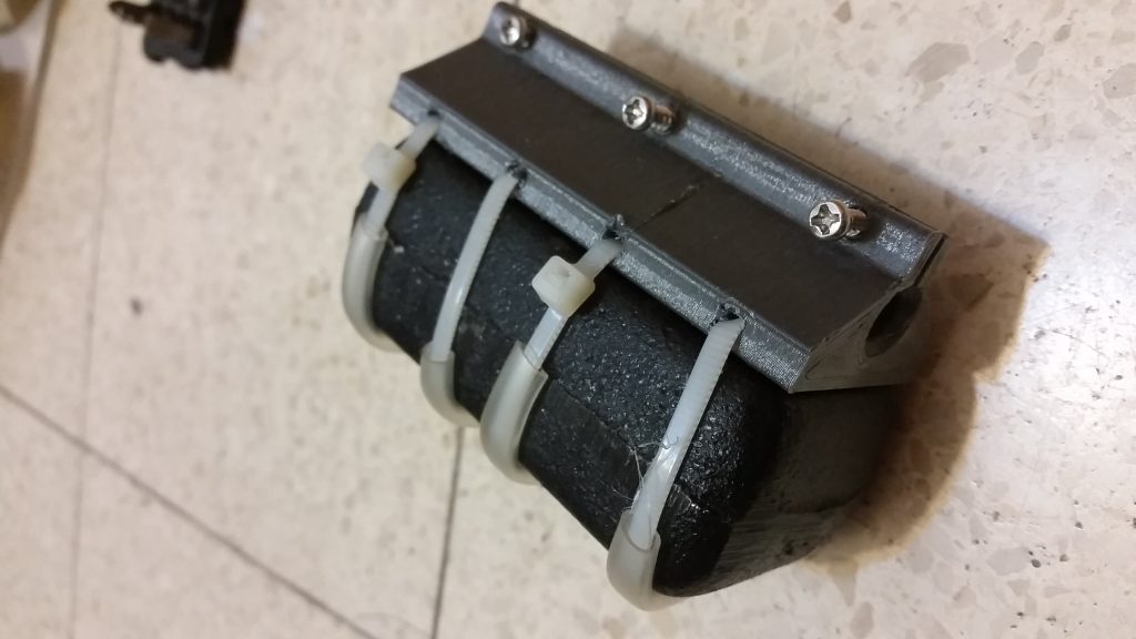
We then clamp the zenith shaft to the balancing shaft (8mm), using the zenith-balancing shaft clamp, and proceed with clamping the weight holder to the balancing shaft (later we will reposition it to balance the Fresnel mirror array):
Fresnel mirror array
Lastly, we clamp the balancing shaft-fresnel mirror adapter to the balancing shaft and glue a broomstick end on top of it, and to the thread of the broomstick, we screw in the Fresnel mirror array.
Solar Sensor
The solar sensor is made out of the solar sensor body, the solar sensor cover, and four LDRs. We glue the LDRs to their place, and solder their legs – four legs are soldered together, and a 5 wire band is soldered to the four free legs and to the common junction. You should also make sure that the wire is long enough to reach the controller.

To avoid a short circuit between the legs, we pot the bottom of the solar sensor body with silicone and snap in the solar sensor cover, and proceed by gluing the sensor to the Fresnel mirror array:
and we are pretty much done with the mechanical part!

Controller
We now need to connect the two motors to the RAMPS MEGA2560 shield. The azimuth should be connected to the x-axis headers, and the zenith should be connected to the y-axis headers. Both stepper drivers are configured to micro-stepping to 1/8 of a step.
Connecting the solar sensor is a bit more complicated, as we need to pull up the four signal lines with external resistors (the internal pull-up resistor is of a much too high value) and connect it to the analog inputs of the controller.
My solution was to solder a small breakout board that connects to AUX-2 header group on the RAMPS board, using 5×2 female headers:
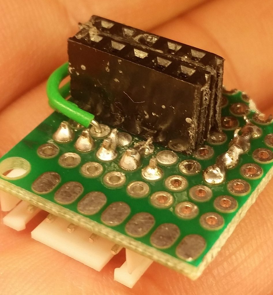
and to solder on a jst-xh 5 pin connector, alongside with 4 pull-up resistors. The result is very messy:
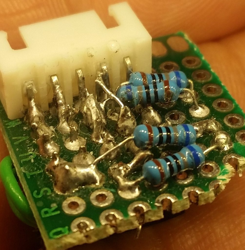
It doesn’t really matter how you solder the board, as long as it follows the schematic:
Power source
To power the motors and the controller I used a custom made pack of 3 lithium-ion batteries (with a protection circuit):
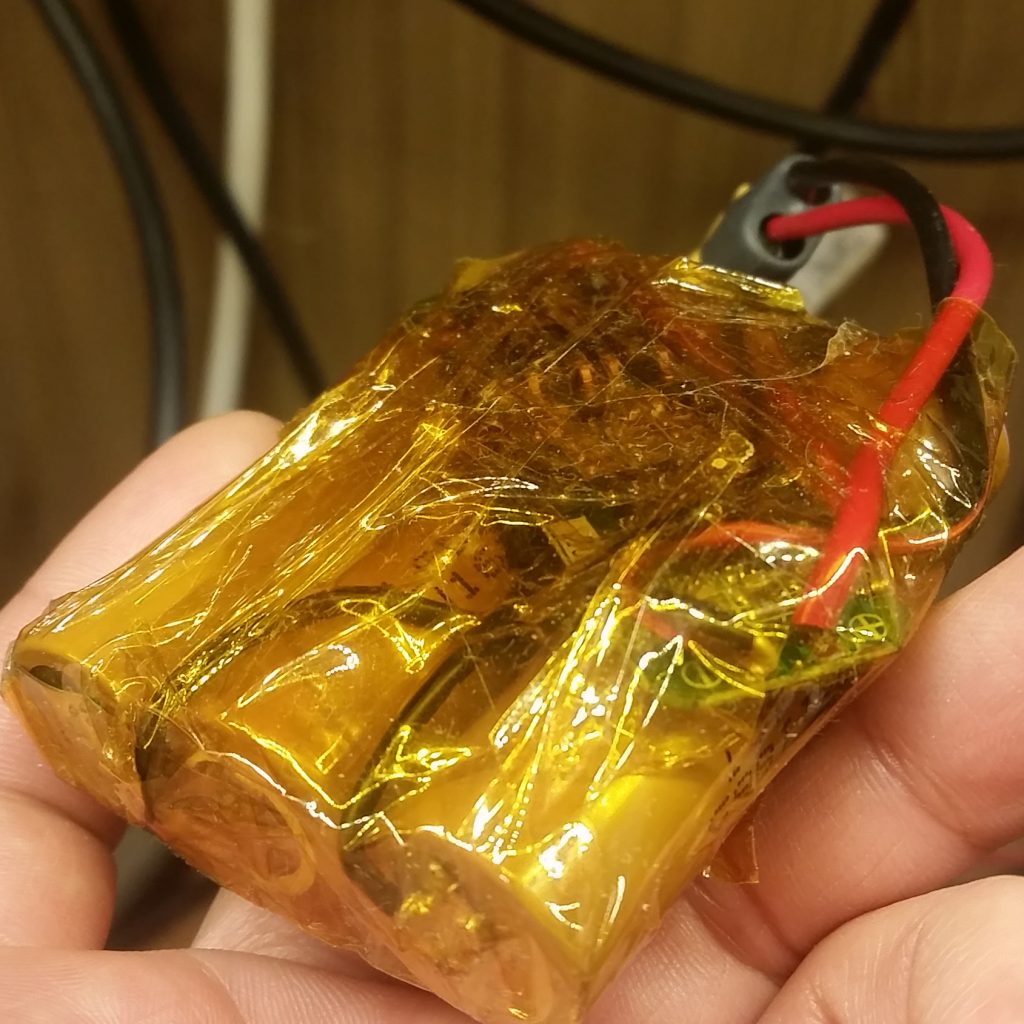
and added a step-up adjusted to 18V. This adds extra torque to the motors which are rated for 12V. I found that it is totally fine to go up to 30V as long as you don’t let the motor run for many minutes without rest (should not happen under normal circumstances of sun tracking), and I must say that the additional torque is very rewarding!

Firmware
The firmware can be found on the GrabCAD project page. We will now discuss the relevant parts of the code.
Notice that you will need to install the Streaming and AccelStepper libraries, both are available on the Arduino library manager.
Configuration
The code starts with configuring the pins of the two motors and the LDRs. If for some reason you want to use another micro-controller or other headers on the RAMPS board, go ahead, just don’t forget to update your choices in the code.
const uint8_t azimuthMotorEnPin = 38;
const uint8_t azimuthMotorStpPin = 54;
const uint8_t azimuthMotorDirPin = 55;

const uint8_t zenithMotorEnPin = 56;
const uint8_t zenithMotorStpPin = 60;
const uint8_t zenithMotorDirPin = 61;

const uint8_t LDRpins[] = {A11, A9, A10, A5};
const uint8_t numberOfLightSensors = 4;
It continues with calculating the angle per step, using mechanical constants, alongside with an optional empirical correction factor. It is not very important for this project, but I’m planning to make a radio telescope in the future with the skeleton, where precise spatial angle determination is crucial.
A more important configuration that must be addressed is the LDR identification, as the firmware needs to know the positions of the sensor:
const uint8_t topRightLDR = 0;
const uint8_t topLeftLDR = 1;
const uint8_t bottomLeftLDR = 2;
const uint8_t bottomRightLDR = 3;
The convention is such that the sensor is viewed from above. To validate that the positions are indeed correct, use the reportSolarReading() function, and shade each sensor, one by one, to see that it is rightfully placed. If not, then modify the indexes above to the correct position.
Additional configurations for the tracking algorithm are the following:
const uint32_t azimuthCorrectionFator = 1000;
const uint32_t zenithCorrectionFator = 1000;
const uint16_t trackerAccuracyThreshold = 20;
const float trackerHysteresisFactor = 2;
The first two, determine the response strength to the correction signal. They multiply the error signal coming out of the solar sensor. While higher values will make the mirror array move faster toward the sun, they would also jitter more around it. Smaller values will make it lock more slowly but would reduce jitter as well. Try these values as a starting point, and then fine-tune them if you dislike the response of the mirror array.
The purpose of the two other constants is to avoid jitter and to define a “stop tracking” condition. When the correction signal is under a certain threshold, and the tracker is directed at the sun at a satisfactory precision, it stops the stepper motors. It turns them on only when the threshold goes higher than the stop tracking value by a factor. This provides hysteresis, to prevent the motors from turning on and off when the value is close to the threshold. Turning off the motors is crucial as it saves a lot of battery life, and prevents the motors from overheating if they are over-voltaged by much.
Solar readings
In each reading cycle of the solar sensor, we read the voltage over the LDRs, which is the response of the voltage divider of the LDR with the pull-up resistor. The higher the light intensity is, the higher the reading value.
void updateSolarReadings()
{
	for (uint8_t i = 0; i < numberOfLightSensors; i++)
		lightIntensities[i] = analogRead(LDRpins[i]);

	azimuthLightIntensityGradient = (lightIntensities[0] + lightIntensities[3]) - (lightIntensities[1] + lightIntensities[2]);
	zenithLightIntensityGradient = (lightIntensities[0] + lightIntensities[1]) - (lightIntensities[2] + lightIntensities[3]);
	lightIntensitySum = lightIntensities[0] + lightIntensities[1] + lightIntensities[2] + lightIntensities[3];
}
Right after reading the four intensity values, the intensity of the two left sensors is subtracted from that of the two right sensors. This value is named “azimuthLightIntensityGradient”.
The sum of all signals together is also calculated, and is used to normalize the response signal (as we will see in the next section) to adapt to different light intensities (such as cloudy days vs. sunny days).
Tracking algorithm
The algorithm is actually very simple, it begins with calculating the correction signal for the zenith and the azimuth:
float correctionSignal()
{
	return -(float)correctionFator * lightIntensityGradient / lightIntensitySum;
}
The signal is just the normalized gradient of the light intensity for the azimuth/zenith, multiplied by the preconfigured factor we discussed earlier.
The algorithm then checks if the mirror array is directed to an acceptable margin. If so, it turns off the motors, and turns them on only when the mirrors are astray by an additional value (providing hysteresis).
if (motorEnabled && (abs(correctionSignal) < trackerAccuracyThreshold))
	disableMotor();
else if (!motorEnabled && (abs(correctionSignal) > trackerHysteresisFactor * trackerAccuracyThreshold))
	enableMotor();
Finally, the correction signal is fed into the motor driver handler:
motor.move(correctionSignal);
Where the command ‘move’ tells the motor to move by ‘correctionSignal’ steps, where positive values rotate the motor in one way, and negative in the other.
Testing it out
Now that everything is assembled, wired and programmed, we are ready to evaluate how well it tracks light.
My first test was simple, it was evening at twilight, the lamp in the living was turned on and the solar array was initially locked to it. When I turned off the lamp, the solar array began in searching the next prominent light source – the setting sun:
I devised a simple test where a laser was attached to the mirror array, right next to the solar sensor, marking the direction of the sensor, and a headlamp was strapped to my forehead so that the mirror array would follow me (as I was the brightest light source in the room). To avoid getting blinded by the laser I wore a blank paper on my face:

And it performed nicely!!!
Being happy with the result, I woke up the next day, powered up the solar cooker and let it find the sun outside the window:
and here is an image of the focused light, scattered on a piece of paper:

Conclusion
In this post I have shared a design for a moving a solar device that uses cheap common parts. The design is also light-weight and easy to disassemble, so it can be packed up and reassembled somewhere else (besides the Fresnel mirror array showed here, but there are lighter and less cumbersome solar devices that you can build yourself and attach to the tracking design).
I’ve also demonstrated a very simple solar sensor alongside a simple algorithm for tracking the sun, and made a rough demonstration of its accuracy.
In the future I plan to build a device that can hold a pan and move alongside the mirror array, and hopefully cook an egg =D
I am also planning to use the device for something much more exciting! I want to build a radio telescope and overlay panorama images of my neighborhood with radio images!!! This will probably be my next book-long post, and I hope it will be interesting enough for people to make it.